
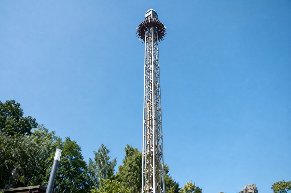
A drop tower purchase is decided on three numbers: structure height, seats per cycle and cycle time. Height sells the ride to guests; seats per cycle divided by cycle time sets the hourly throughput your gate receipts depend on. Braking architecture and site infrastructure decide whether the machine can be installed, inspected and operated at your location. This guide sets out how to compare quotations line by line, what to verify in the braking specification, and what your site must supply before a tower can be delivered. Current models are listed on our drop towers for sale page.
Start with throughput, not height
Procurement teams often open with height because it is the headline figure in the brochure. Throughput is the figure that determines payback. The calculation is straightforward:
Hourly throughput = (seats per cycle × 3600) ÷ cycle time in seconds × loading efficiency
Cycle time runs from the moment the cabin is confirmed secure to the moment the next cabin is ready to load. It includes ascent, the hold at the top, the drop, braking, descent or return of the cabin, and restraint release. Loading efficiency is the share of a nominal hour actually spent cycling; a figure between 0.75 and 0.90 is realistic once you account for slow boarding, guests who change their minds and short stoppages.
Worked example
Take a tower with S seats per cycle and a cycle time of T seconds, at loading efficiency E.
- Cycles per hour = 3600 ÷ T
- Guests per hour = S × (3600 ÷ T) × E
With S = 24, T = 90 s and E = 0.85: cycles per hour = 40; guests per hour = 24 × 40 × 0.85 = 816. If the same tower runs a 120 s cycle, throughput falls to 612. If a competing quotation offers 16 seats at a 60 s cycle with the same efficiency, it delivers 816 as well — from a shorter tower with a smaller cabin. The two are not equivalent purchases: one carries more guests per cycle and a longer queue tolerance, the other cycles faster and needs more dispatches per hour from your operators.
Ask each supplier for the cycle time broken into its phases, not a single figure. Then model your peak-hour queue against the throughput you calculate, not the throughput printed in the proposal.
What actually sets the price
Two towers of the same height can differ substantially in cost. The drivers, in rough order of influence:
- Structure height and section count. Taller towers need more mast sections, more guying or a heavier base, and larger lifting equipment on site.
- Cabin seats. Seat count drives cabin mass, restraint count, the number of harness checks per dispatch and the braking capacity required.
- Braking system. Magnetic (eddy-current) braking with a friction or hydraulic final-stop stage costs more than a purely friction arrangement, and the redundancy built around it costs more again.
- Redundancy. Duplicated sensors, dual braking paths, backup power for controlled descent and independent overspeed detection all carry cost — and all appear in the risk assessment your insurer will read.
- Theming and enclosure. Cladding, lighting, queue-line build and station roofing are frequently quoted as options; confirm whether they are in or out of the base figure.
- Foundation. Pile or raft design depends on your soil report. A supplier quoting a foundation allowance without your geotechnical data is estimating, not designing.
- Installation method. Crane-erected mast sections versus a self-climbing sequence change both the installation cost and the site access you must provide.
Ask for the quotation split into these categories. A single lump sum cannot be benchmarked against a competing bid.
Braking: why magnetic braking is specified and what to verify
Magnetic braking uses eddy currents induced in a conductor as the cabin passes the brake fins. There is no contact wear surface in the primary braking phase, braking force rises with speed, and the stop is progressive rather than abrupt. That combination is why it is commonly specified for drop towers: it reduces the mechanical wear that a purely friction brake would see on every cycle, and it produces a deceleration profile that is easier to control across the passenger mass range.
Magnetic braking does not bring the cabin to a final standstill on its own at low speed. A secondary system — friction, hydraulic or a controlled final-stop arrangement — completes the stop and holds the cabin. Verify the following in each quotation:
- The braking architecture in writing: primary and secondary stages, and how each is triggered.
- How the brake is sized — against cabin mass at maximum load, and against the drop height. Ask for the design basis, not the component model.
- What happens on loss of power mid-cycle, and what the documented descent or recovery procedure is.
- Overspeed detection: how many independent sensors, how they are tested, and at what interval.
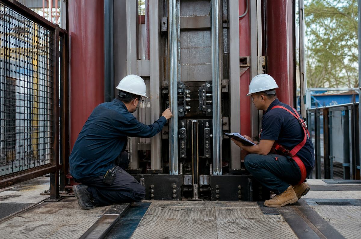
- Daily and annual inspection requirements for the braking path, and the spare parts list that supports them.
- Which standards the braking design is assessed against — stated as the standards required by your destination market, confirmed per project.
What your site must provide
The supplier delivers the ride; the site delivers the conditions for it. Confirm each of the following before signing:
- Foundation and geotechnical report. The tower foundation is designed to your soil conditions. Commission the geotechnical survey first and pass the report to the supplier; foundation drawings follow from it.
- Power supply. Confirm the supply capacity, voltage and phase configuration the ride requires, the distance from the connection point, and whether a dedicated transformer or generator backup is needed for controlled evacuation.
- Access for delivery and erection. Mast sections and the cabin arrive by road; the crane or lifting arrangement needs a standing area and a route with adequate load capacity and turning radius. Confirm dimensions with the supplier before scheduling transport.
- Evacuation route. A documented means of recovering guests from the cabin at height, and from the station, agreed with your local authority. This affects the tower's position on the plot, not just its operation.
- Wind exposure. The operating wind limit is set per project from the tower height and local wind data. Confirm the limit, the anemometer position and the shutdown procedure, and check whether surrounding structures create turbulence at the tower.
- Operating and maintenance staffing. Dispatch staffing per cycle, and the technician hours required for daily checks, follow from the cycle time and brake inspection schedule.
Ten questions to ask each supplier
- What is the cycle time, broken into ascent, hold, drop, braking and unloading phases?
- What seats-per-cycle and loading efficiency did you assume for the throughput figure in your proposal?
- What is the braking architecture, and how is the brake sized against cabin mass and drop height?
- What redundancy is included as standard, and what is optional?
- Which standards is the design assessed against for our destination market, and who confirms that per project?
- What foundation input do you need from us, and is foundation design in your scope?
- What are the power, access and crane requirements at our site?
- What is the delivery and installation sequence, and how many of your technicians attend?
- What is the spare parts list for the braking and restraint systems, and what are the lead times?
- What documentation is handed over — drawings, inspection schedules, operating manual, training records?
Delivery and installation sequence
A typical sequence runs: factory acceptance and pre-shipment inspection; shipping and customs clearance; site handover of the prepared foundation; erection of mast sections and cabin; electrical and control installation; no-load and load testing of the braking path; commissioning and staff training; then handover of documentation. Confirm which stages are witnessed by your team or a third party, and build the schedule backwards from your opening date with contingency for foundation curing and customs.
Quotation comparison table
| Quotation line item | Why it matters | What to verify |
|---|---|---|
| Structure and mast sections | Sets erection method and crane requirement | Section count, transport dimensions, lifting plan |
| Cabin and restraints | Drives seats per cycle and dispatch time | Seat count, restraint type, harness check procedure |
| Braking system | Core safety and wear item | Primary and secondary stages, sizing basis, overspeed detection |
| Redundancy package | Affects insurer review and uptime | What is standard versus optional, and backup descent provision |
| Theming and enclosure | Often excluded from base price | Whether cladding, lighting and station build are included |
| Foundation | Depends on your soil report | Whether design is in scope and what geotechnical input is required |
| Installation and commissioning | Determines site readiness and schedule | Technician count, duration, testing and training included |
| Documentation and spares | Supports inspection and uptime | Drawings, inspection schedule, spare parts list and lead times |
Next step: send your site plan, geotechnical report and target throughput to our team, and we will return a quotation structured against the table above. Review the current range on our drop tower for sale page, or browse the full drop tower product category for height and seat configurations.