Drop Towers

Time Gate

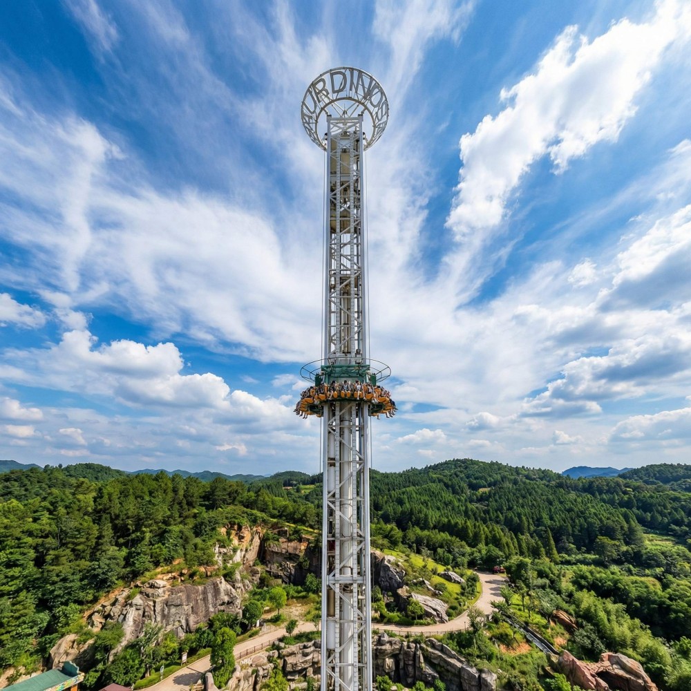
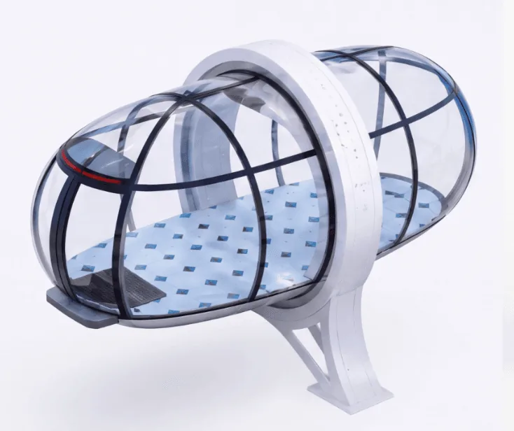
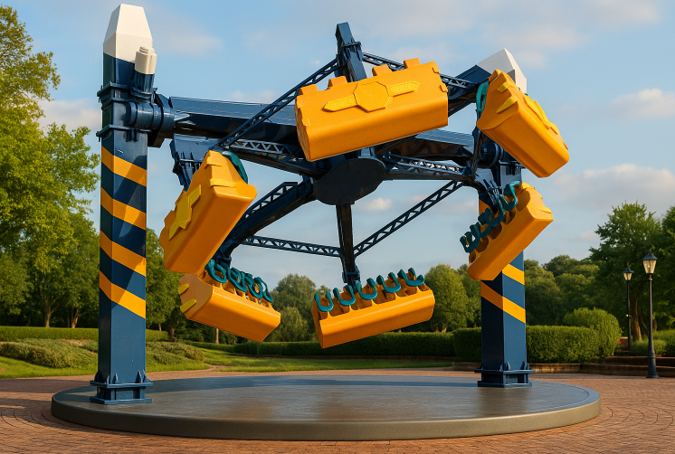
The Time Gate is a drop tower ride that combines vertical lift, rotation and tumbling for a thrilling experience. It suits parks seeking a high-capacity, visually striking attraction.

Ride durationApproximately 240 seconds
Lift height0.5 meters before rotation
Drive typeHydraulic system with moving pulley

Specifications

Figures below are the design values for this model. Site-specific engineering is confirmed per project.

Ride durationApproximately 240 seconds
Lift height0.5 meters before rotation
Drive typeHydraulic system with moving pulley
Rotation controlIndependent variable frequency drives
Descent speed (failure mode)Not exceeding 0.5 m/s
Response timeAs low as 0.1 seconds
Speed control accuracy±0.1%
Rescue modeManual operation for slow descent

Engineering & Craftsmanship

Overview

The Time Gate is a drop tower ride that combines vertical lift, rotation and tumbling motions. Passengers experience a sequence of lift, clockwise and counterclockwise rotation, and tumbling before a controlled descent. The ride cycle lasts approximately 240 seconds. The cabin rotates to a head-up position before lowering. The ride is designed for parks seeking a dynamic attraction with a striking appearance and lighting.

Design and build

The lift system uses hydraulic cylinders connected to a moving pulley, which doubles the lifting stroke while conserving installation space. This hydraulic approach provides smooth control of the lifting speed on both columns, keeping the crossbeam level. A backpressure braking system and an anti-reverse device ensure stable tumbling and rotation. The system includes pressure relief valves and electrical interlocks to prevent overpressure. In the event of pressure loss, the descent speed is limited to 0.5 m/s. A manual rescue mode allows slow lowering of passengers during power failure.

The drive system uses planetary gear reducers with a compound transmission structure. This design handles the off-center loads that occur during tumbling. Each motor is controlled by an individual variable frequency drive, allowing precise adjustment of speed and torque. The system response time can be as low as 0.1 seconds, with speed control accuracy of ±0.1%. This independent control ensures accurate positioning of the cabin for safe descent. The planetary reducers also contribute to smooth operation and low noise.

Site and installation

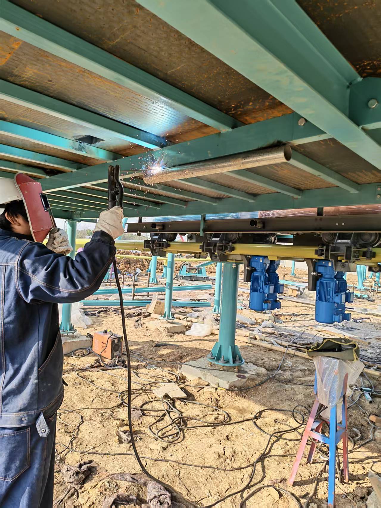
The Time Gate requires a foundation designed for the ride's dynamic loads. Installation should be carried out by qualified personnel following the manufacturer's instructions. The hydraulic system and electrical components must be protected from environmental factors. The ride is designed to the standards required by your market, confirmed per project. Site preparation should include adequate space for the ride footprint and surrounding clearance. Power supply and control systems must meet local codes. The compact hydraulic lift design reduces the required installation height.

Operating notes

Daily inspections should include checking hydraulic fluid levels, pressure gauges, and the condition of hoses and fittings. The anti-reverse device and backpressure braking system must be tested regularly. The manual rescue mode should be verified during maintenance. The control system allows for precise adjustment of rotation and tumbling speeds. Operators should monitor the ride during operation and be prepared to use the emergency stop if needed. The ride is intended for use in accordance with the operating manual and local regulations.
Frequently asked questions

The questions park developers ask most about this ride — answered without the sales language.

01What is the ride cycle time?

The complete ride cycle lasts approximately 240 seconds, including lift, rotation, tumbling and descent. This duration allows for a full experience while maintaining throughput. Actual cycle time may vary slightly based on operational adjustments.

02How does the ride handle power failure?

In case of power failure, a manual rescue mode allows operators to slowly lower passengers to the ground. The hydraulic system is designed to limit descent speed to 0.5 m/s under pressure loss, ensuring a controlled evacuation.

03What maintenance is required?

Regular maintenance includes checking hydraulic fluid levels, inspecting hoses and fittings, testing pressure relief valves, and verifying the anti-reverse device. The manual rescue mode should be tested periodically. A detailed maintenance schedule is provided in the operation manual.

Request a Consultation

Tell us about your project. Our engineering team will respond within 24 hours.

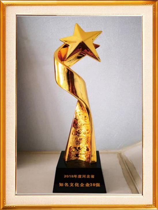
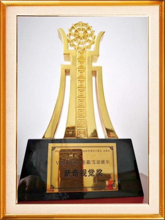
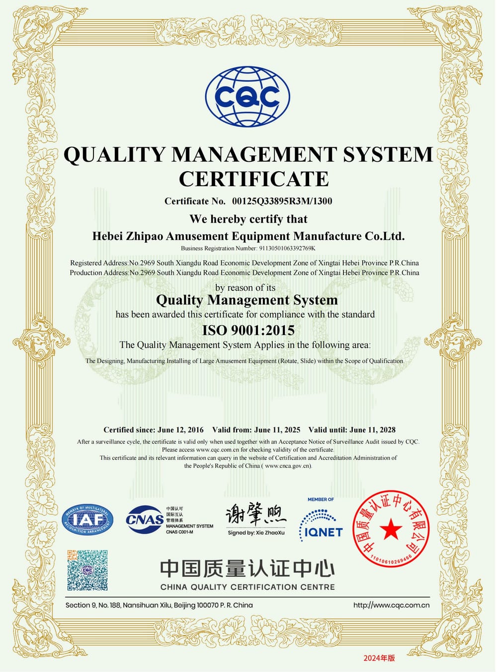
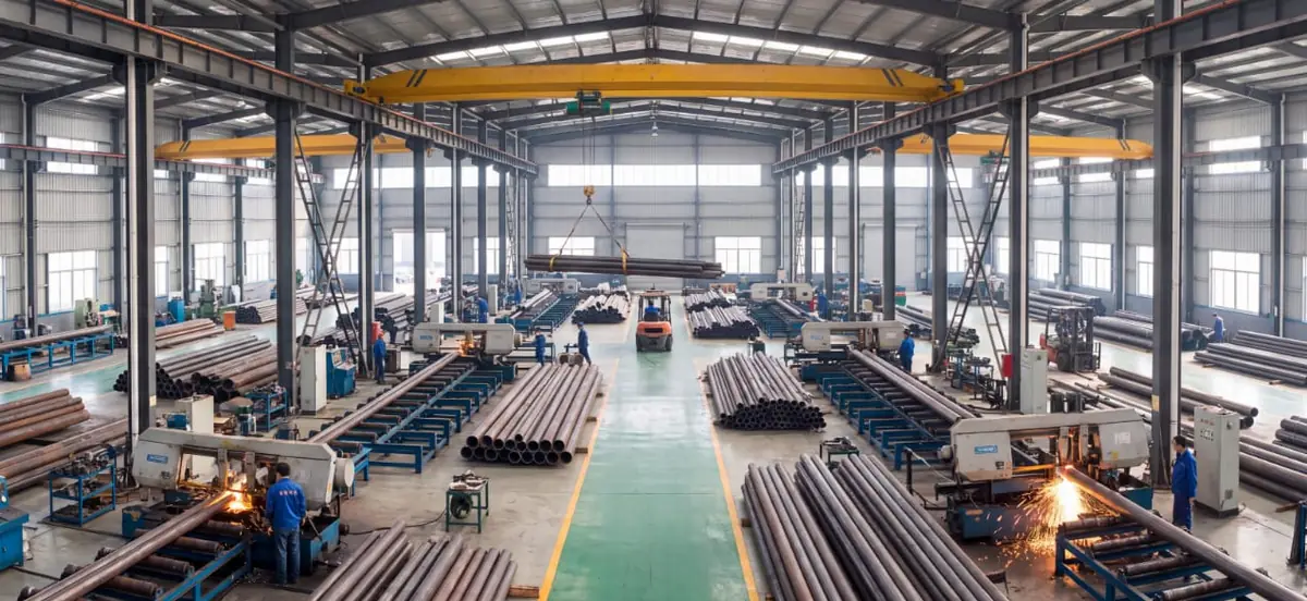
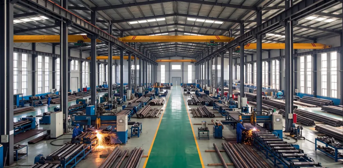
Certificates & manufacturing

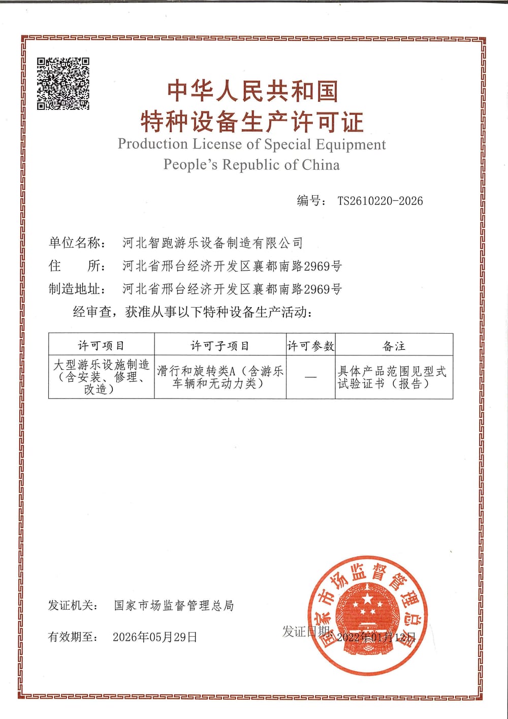
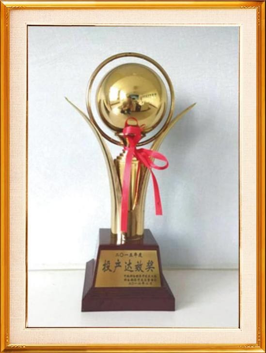
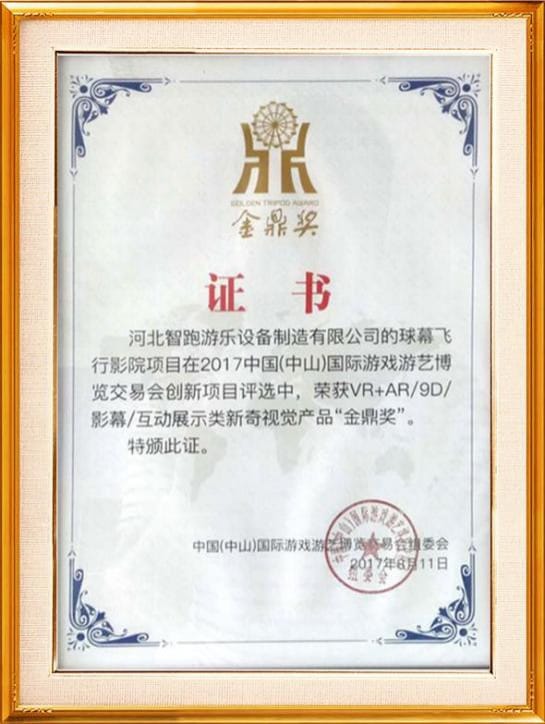
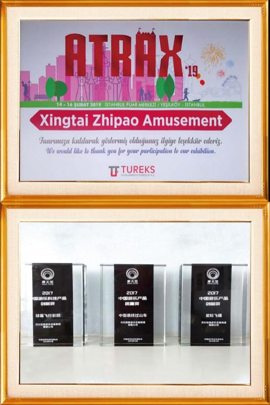
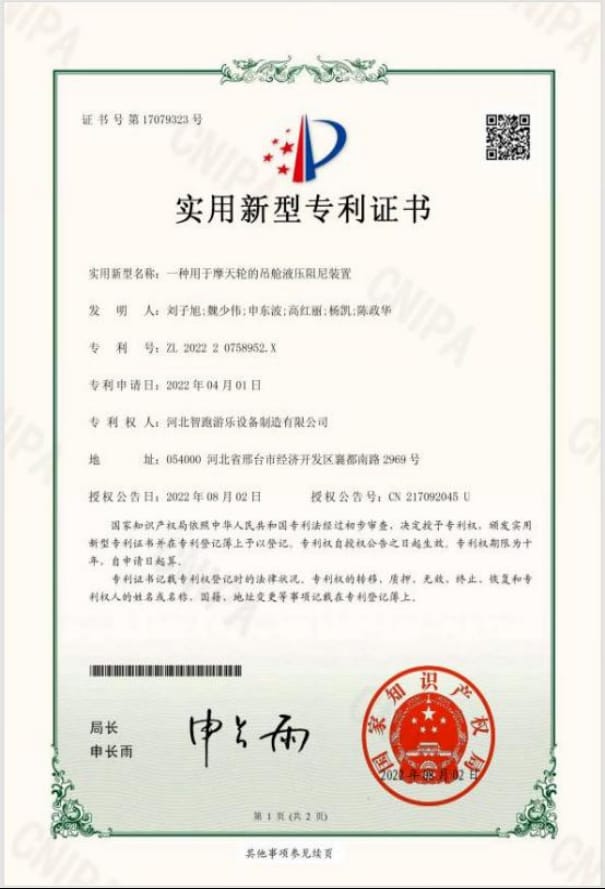
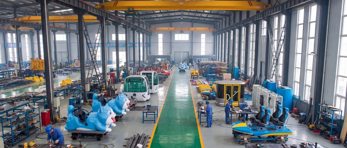
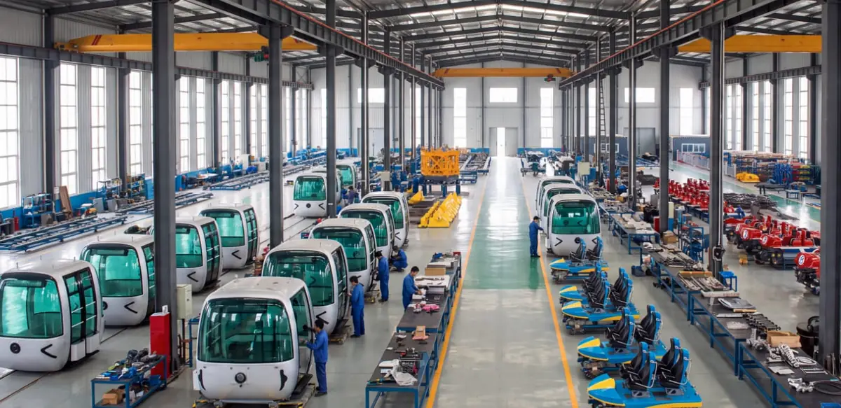
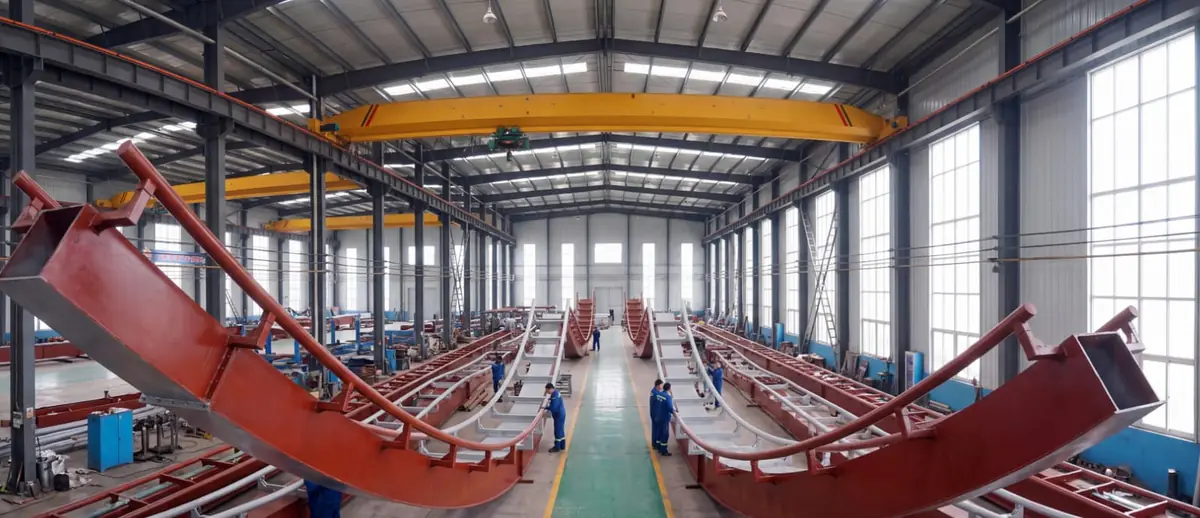
The same factory, quality process and certification documents stand behind every ride below — reviewed once here rather than repeated on each product page.

01Compliance

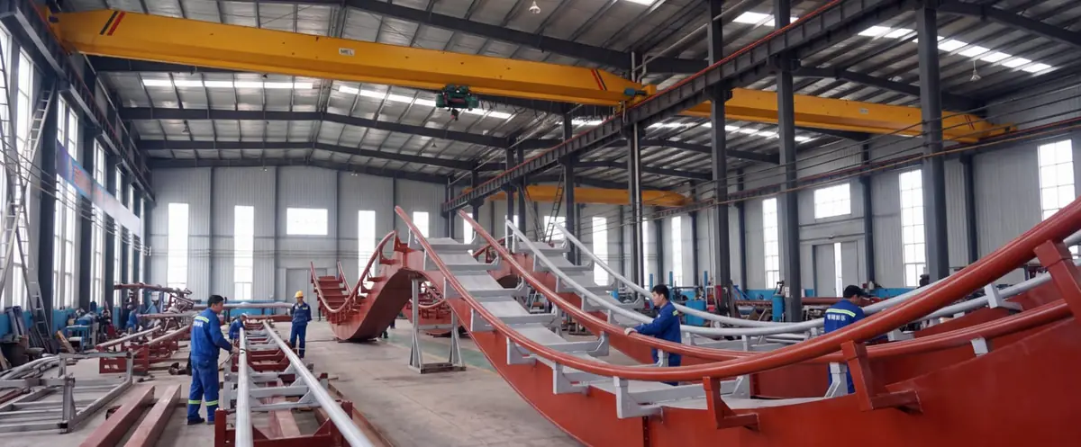
Manufacturing and quality control

  • Standards scoped per market

    Design basis agreed against the standards your market requires, confirmed per project

  • Long design service life

    Structure designed for a 20-year service life, stated in the contract for each project

  • Full-Process NDT Inspection

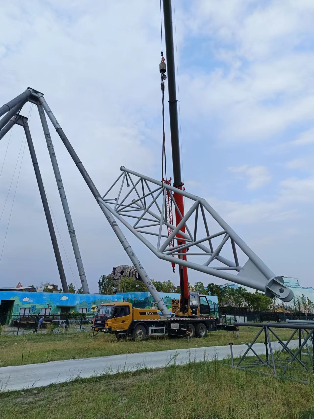
    Rigorous non-destructive testing at every production stage

02Core Technology

Cable wheel structure

  • Corrosion protection

    Advanced surface treatment for extreme environments

  • Optimized Mechanical Performance

    Lightweight yet high-strength for wind resistance

  • Construction & Aesthetic Dual Advantage

    Faster installation with premium visual finish

  • Quick-Release Fault Mechanism

    Integrated emergency release system for minimal downtime

03Hardware

Landmark-Grade Specifications

  • 90m Ultra-High Landmark Scale

    Iconic skyline-defining structures

  • High Passenger Throughput

    Maximum revenue efficiency with large cabin capacity

  • All-Climate Comfort

    Thermostatic cabins for year-round comfortable riding

  • Redundant Multi-Motor Drive

    Multi-motor configuration for fault tolerance

  • Compact Footprint Planning

    Space-efficient layout for flexible site integration

04Safety

Multi-Layer Safety Protection

Every ZhipaoRides product is engineered with redundant, fail-safe systems that meet or exceed international amusement ride safety standards. From electrical interlocks to structural redundancy, we leave nothing to chance.

  • Mandatory Safety Interlock

    Forced electrical interlocking prevents any unauthorized or unsafe startup. The system requires all safety conditions to be met before operation can begin, eliminating human-error risks.

  • Triple-Layer Cabin Door Protection

    Three independent door opening safeguards — mechanical lock, electrical sensor, and control system verification — eliminate passenger entrapment risk under all operating conditions.
  • Redundant Braking System

    Dual independent braking mechanisms with fail-safe engagement ensure controlled deceleration even in the event of primary system failure, meeting Class A ride standards.

  • Real-Time Condition Monitoring

    Continuous sensor-based monitoring of vibration, temperature, and load distribution provides instant anomaly detection and automatic shutdown when parameters exceed safe thresholds.

  • Emergency Evacuation System

    Integrated auxiliary drive and manual release mechanisms enable safe passenger evacuation from any position, including during power outages or extreme weather conditions.

  • Full-Life NDT Quality Control

    Non-destructive testing at every production stage — from raw material to final assembly — ensures structural integrity backed by 25-year design life certification.

Our safety systems undergo rigorous third-party testing and certification to meet or exceed GB 8408 (Chinese national standard) and EN 13814 (European standard) requirements. Each ride is equipped with multiple redundant safety mechanisms, ensuring passenger protection at all times. From the factory floor to the final installation site, our engineering team conducts comprehensive safety audits, load tests, and operational simulations before any ride enters service.