Overview
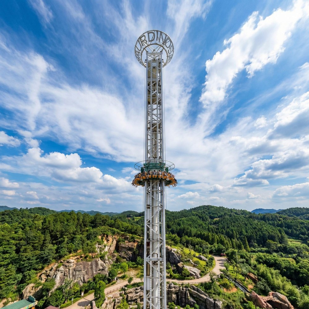
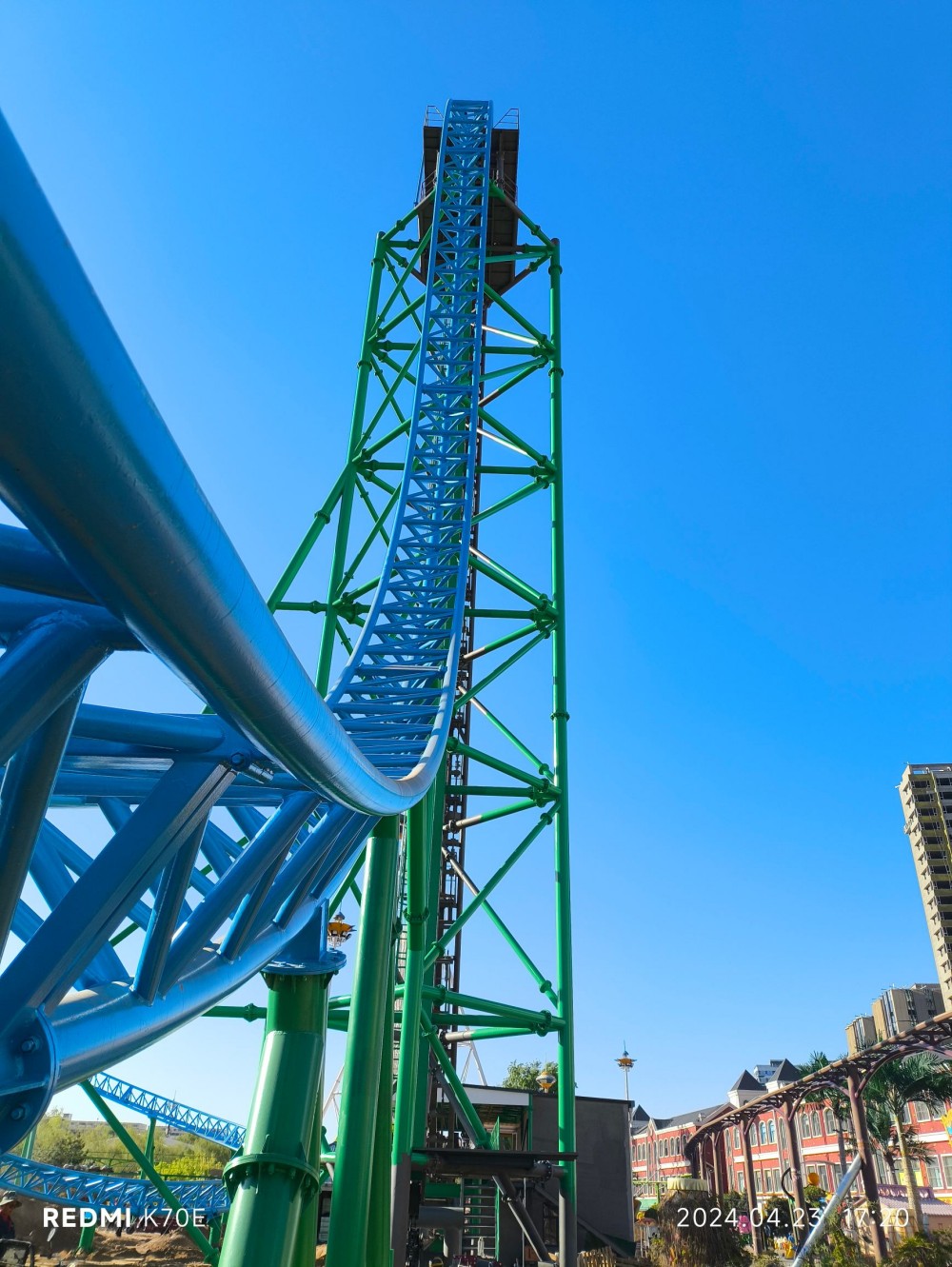
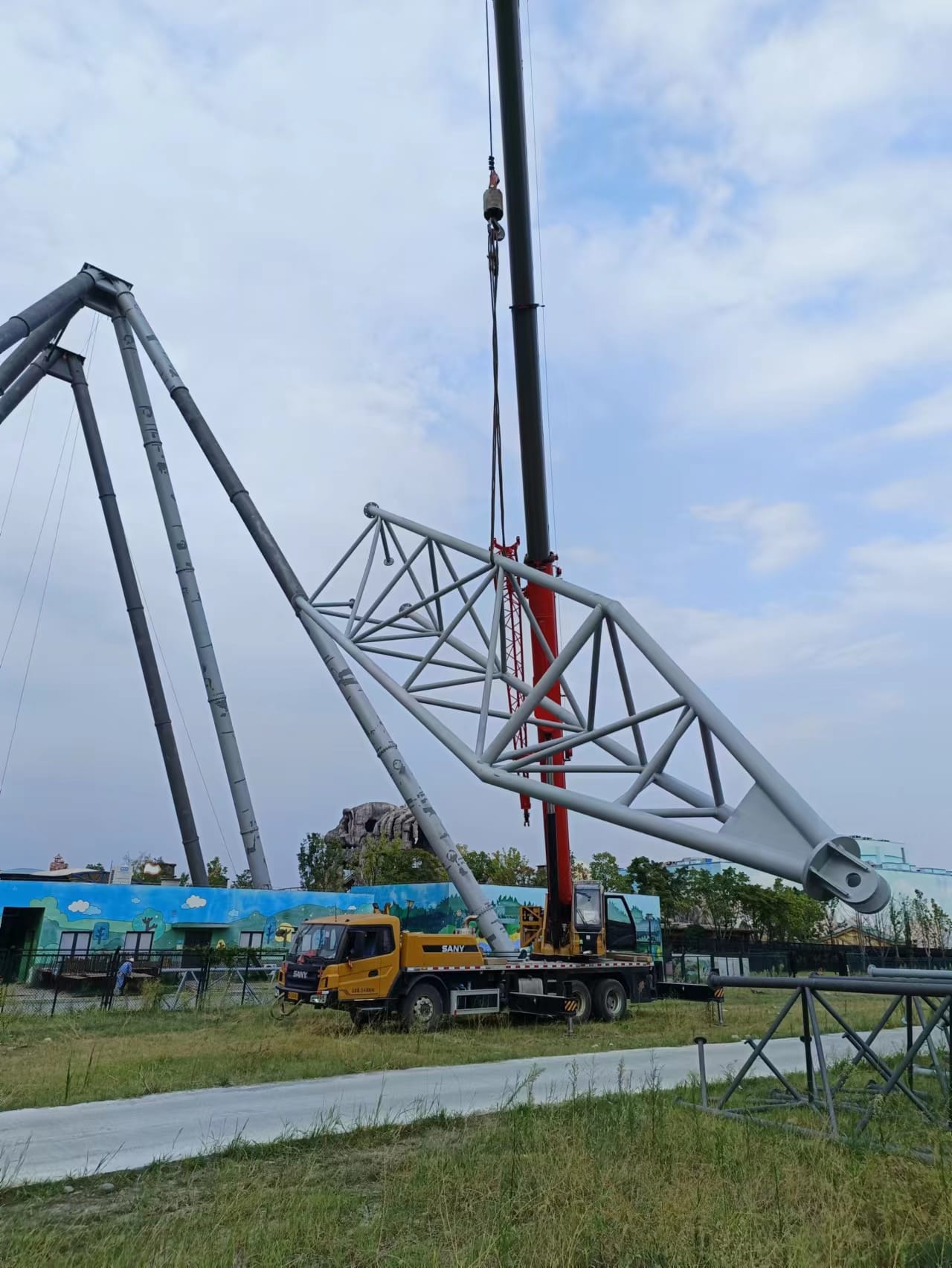
The Free Fall is a drop-tower ride in the flying-tower category. A single cabin carries 20 riders to a run height of 45 m and then performs a sequence of controlled drops and stops. The ride is intended for park developers and investors who need a compact, high-capacity thrill attraction with a clear procurement path.
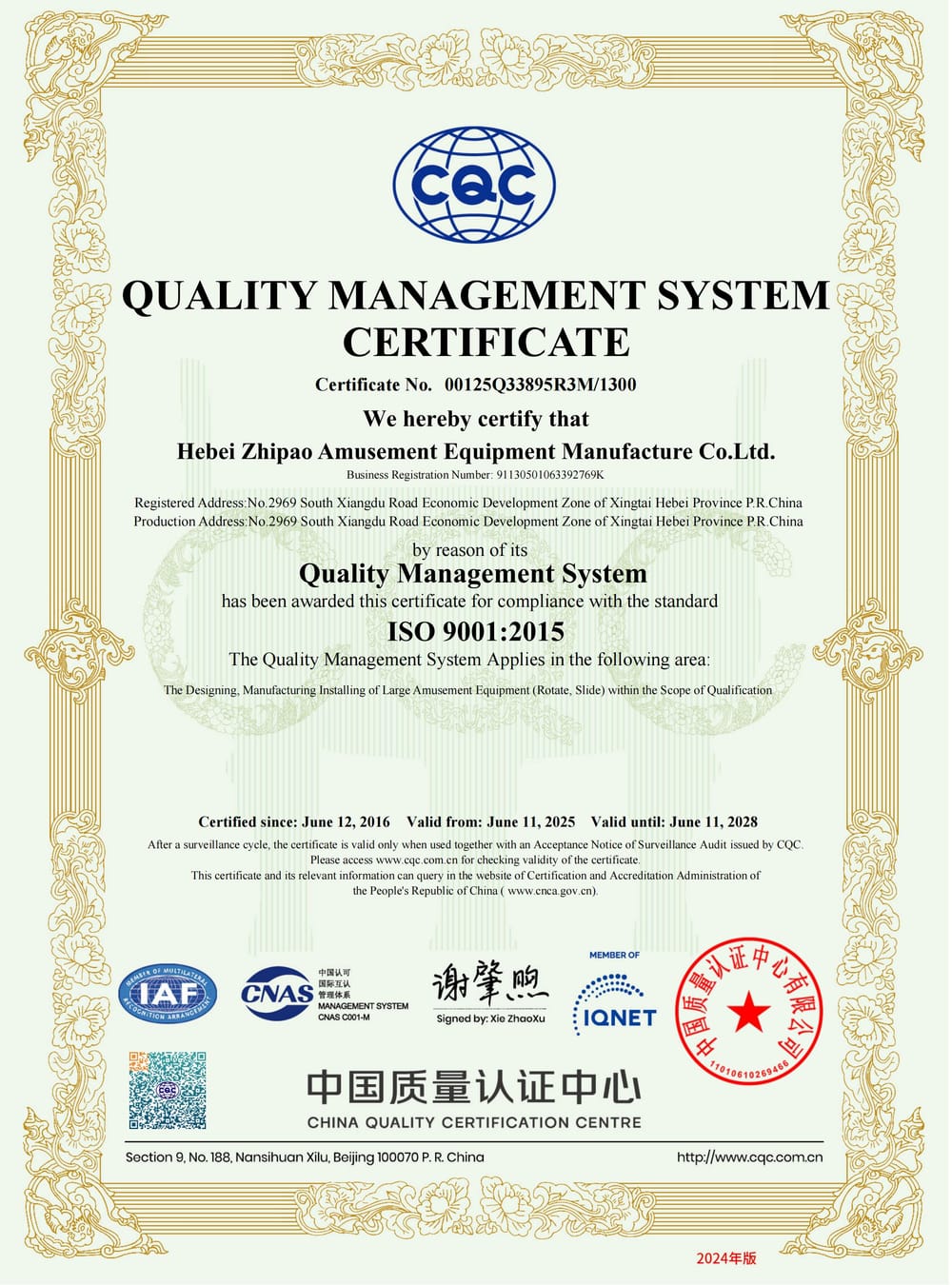
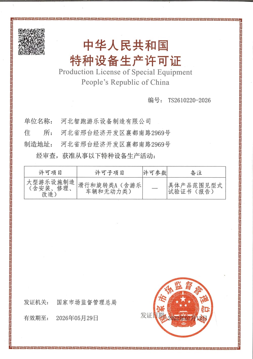
With a total equipment height of 53 m and a cycle time of 180 seconds, the ride can be planned into a range of park layouts. It is designed to the standards required by your market, confirmed per project.
Design and build
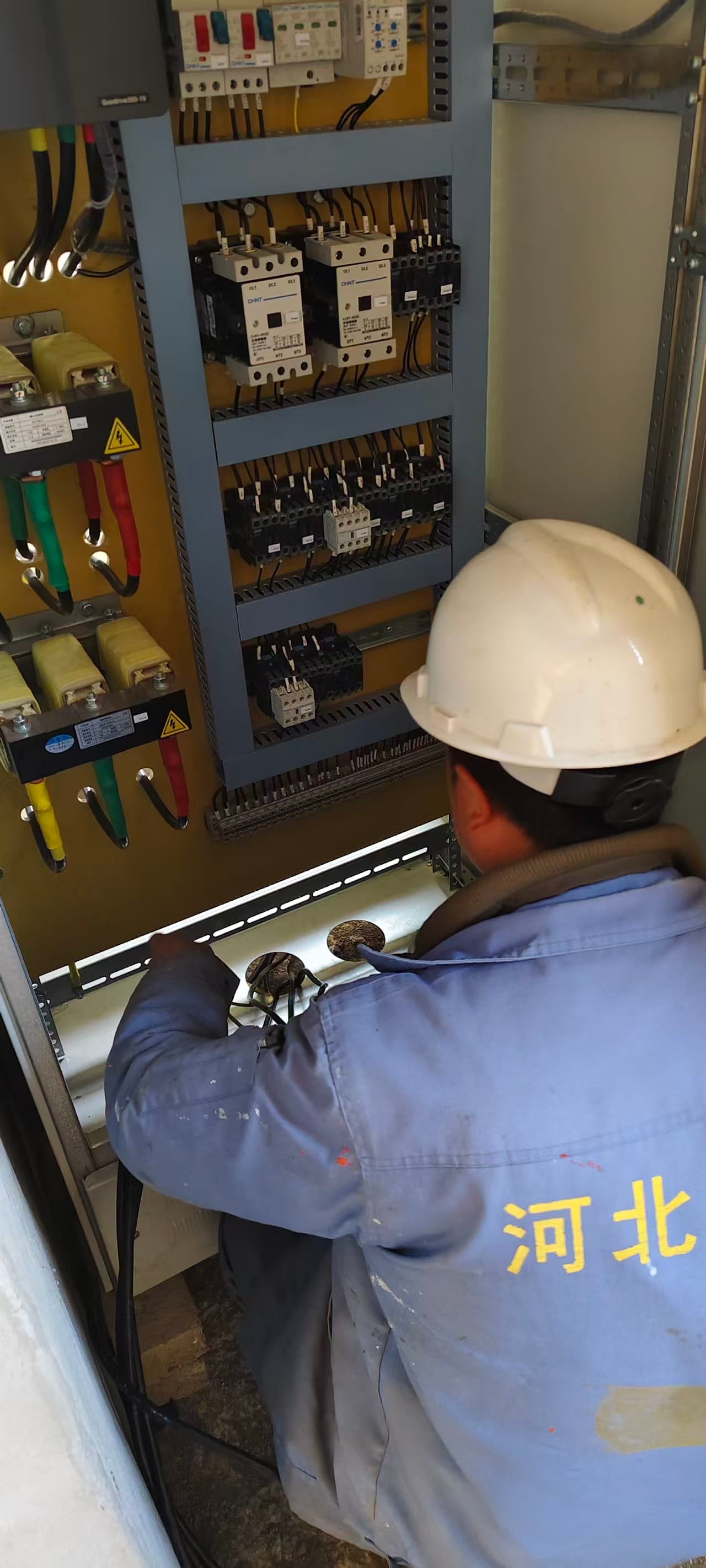
The cabin travels on a vertical column track. Upward and downward motion is driven by a pneumatic system, which supports the repeated acceleration and deceleration pattern of a drop tower. The restraint system uses a dual locking arrangement with position and lock interlocks. The ride will not start unless the restraints are closed and locked.
- Pneumatic pressure interlock: the ride cannot start if system pressure is below 0.7 MPa.
- Rope-break detection interlock: the ride cannot start if a rope fault is detected.
- Seat shells are glass-reinforced plastic and can be customised for park theming.
- Restraints include soft material and a front seat belt for comfort and operation.
- A gas-liquid buffer is fitted at the base of the main structure.
No proprietary engineering details, component brands or load figures are disclosed in this summary.
Site and installation
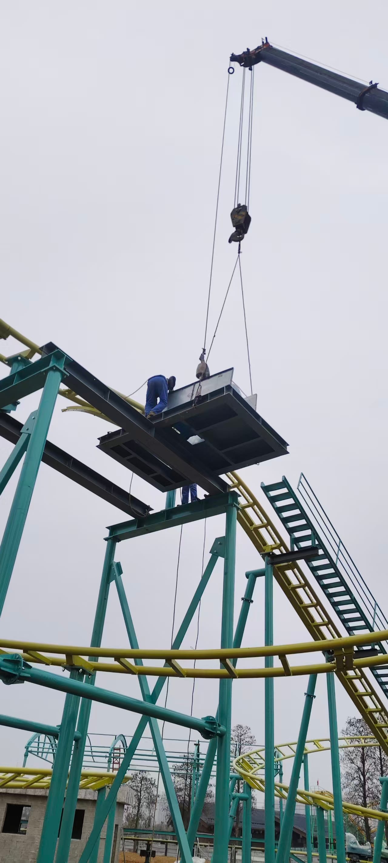
The ride occupies a footprint of 12 m by 18.5 m. The equipment height is 53 m, so local height restrictions and clearance requirements should be checked early in planning. Power supply is 3N+PE 380V/220V 50Hz, with an installed capacity of 163 kVA. The design service life is 16 years.
Foundation design, anchor details and site-specific engineering are confirmed per project. Buyers should provide soil data and site drawings so that the installation scope can be defined.
Operating notes
The ride cycle is 180 seconds for 20 riders. Operating procedures should include daily checks of restraint interlocks, pneumatic pressure and rope condition. The control system supports a maintenance mode for manual cabin descent.
- Emergency plan A: switch to maintenance mode and lower the cabin manually, then release restraints and evacuate.
- Emergency plan B: if maintenance descent is not possible, isolate power and use the manual valve for slow descent; use emergency power to open restraints.
- If the cabin is below 4 m during plan B, place rescue supports at diagonal positions before entering the structure.
Training for operators and rescue staff is part of the handover package. Spare parts and service intervals are agreed per project.